Jdm-040 Schematic Guide
When the blue light finally pulses again, it’s more than just a fixed gadget—it's a victory for the "Right to Repair" community, proving that even without an official map, a dedicated group can decode the silicon.
: Filters on the main power lines heavily rely on 10µF, 0603-sized SMD capacitors . 2. Analog Joystick Potentiometers
A small, delicate connector (3-pin) that feeds into the mainboard. B. The MCU (Microcontroller Unit)
The JDM-040 schematic boasts several key features that make it a popular choice among DIY enthusiasts: jdm-040 schematic
: Repair diagrams for the JDM-040 highlight specific "vias" (tiny holes in the PCB) that can be used to bypass broken traces for the △triangle
A blown fuse or broken trace near the battery connector.
: The JDM-040 introduced the slim light bar feature. Technicians often note that while it is technically possible to use charging boards from newer models (JDM-050/055), the pin orientation is flipped, requiring a longer ribbon cable to function . When the blue light finally pulses again, it’s
A thin strip of light shines directly through the top of the front touchpad.
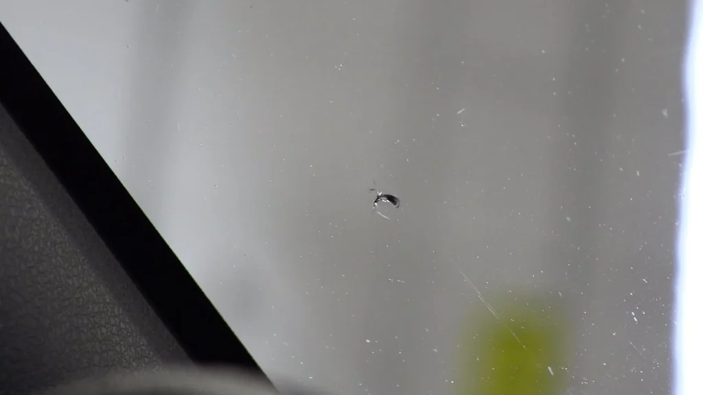
The story of a JDM-040 repair often begins with a "dead" controller. For a DIY enthusiast, cracking open the shell reveals a complex landscape of trace lines and surface-mount components. Unlike older models, the JDM-040 was a significant evolution, moving the light bar to the top of the touchpad and refining the internal power management. The Conflict: The Missing Map
The JDM-040 button matrix operates on an active-low pull-up configuration. The MCU keeps the signal lines at 3.2V. Pressing a button grounds the circuit, dropping the voltage to 0V and triggering the input. Common Diagnoses and Repair Workflows Probable Cause Diagnostic Step Fix Action Completely Dead / No Light Blown PMIC or F1 Fuse Test for 5V at the ribbon connector pads. Replace JDS-040 board or replace the onboard fuse. Severe Stick Drift Worn Potentiometer Tracks Measure resistance between Pin 1 and Pin 3. : The JDM-040 introduced the slim light bar feature
Drives the eccentric rotating mass (ERM) motors for vibration feedback. 3. Common Schematic Repair Points
: Many schematics found online are community-drawn or leaked engineering diagrams. Some may have low resolution, making it hard to read tiny component labels.
Supplies raw battery power to the PMIC.
Before diving into the schematic, you must identify if your controller uses the JDM-040 board. This version is distinguished by its grey buttons visible through the touchpad. Main PCB (JDM-040):
The JDM-040 motherboard represents a major milestone in Sony's DualShock 4 controller evolution. Found inside the Slim and Pro PlayStation 4 console bundles, this board revision introduced the lightbar window on the front touchpad.